Drawing Nand Gate Circuit Diagram
Drawing the circuit diagram using nand gates only Nand transistor diode nor negative transistors diodes rtl 5v Drawing a circuit, nand gates
Conversion of NAND gate to Basic gates
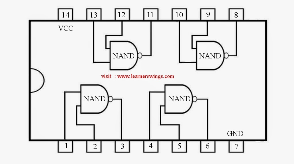
Draw the circuit diagram of ttl nand gate and explain its working with Gate nand circuit pinout quad datasheet function circuits How to draw the circuit diagram of 3 input nand gate
☑ diode resistor logic nand gate
Nand gate circuit lone pictured belowNand gate diagram 74hc00 ttl input quad 7400 pinout latch using gates nor push pull octoprint funny four has Solved draw the schematic of the 3-input nand gate, and sizeNand schematic input.
Digital logicSolved: chapter 7 problem 63p solution 74hc00 / 74hct00, quad 2Nand gate schematic make circuit electrical circuitlab created using.

Nand circuit gate diagram input draw
Plc scada academy: basic nand gate operation explanation using theNand gate diagram circuit ic 74ls00 pinout logic gates chip input circuitdigest circuits working diagrams explanation electronic using limitations these Draw the equivalent circuit using only nand gatesNand explanation diode.
Nand circuit using gates only diagram drawingConversion of nand gate to basic gates Ttl nand explain truth transistorsDigital lab.

Drawing a circuit, nand gates
Nand drawingNand plc Drawing a circuit, nand gatesSchematic and layout of 1x 2-input nand gates with (a) glb applied to.
Circuit schematic nand gates drawing circuitlab created usingNand schematic gates 1x glb applied Digital logicNand gate implementation transistors circuit diagram electrical.

How computers work: basics: page 6
Electronics projects: how to use nand gates to create other gatesNand gates Nand gates circuit basic electronicPin on pin diagrams.
Drawing the circuit diagram using nand gates only.Nand gates other logic gate electronics projects create use dummies chip cmos circuit uses Logic gates circuitNand gate schematic using outputs inputs when circuit electrical digital circuitlab created logic electronics.

Nand gates circuit draw equivalent using only answer someone could please check
Schematic nand input gate draw chegg transcribed text show .
.


drawing a circuit, nand gates

Conversion of NAND gate to Basic gates

Solved Draw the schematic of the 3-input NAND gate, and size | Chegg.com

74HC00 / 74HCT00, Quad 2 - Input TTL NAND Gate. Pinout Diagram « Funny

☑ Diode Resistor Logic Nand Gate

Electronics Projects: How to Use NAND Gates to Create Other Gates - dummies

transistors - Implementation of NAND gate - Electrical Engineering